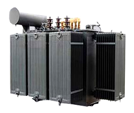
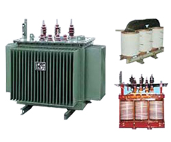
A design for a polyphase distribution transformer is described, with the transformer output pores accurately created in terms of relative phase angle and voltage magnitude for Distribution, Industrial, and Substation Up to 10 MVA, 33kV transformer. The primary and auxiliary transformers in the design are utilised in tandem to create the precisely designed phases. With the auxiliary transform allowing for phase fine tuning, the primary transformer allows for rough phase modification. Such a design is especially appropriate for transformer techniques that call for output phases of a number that are not all equitably divisible by three.
Distribution transformer provides the final voltage transformation in the electric power distribution system which helps in dropping the voltage in the distribution lines to the level needed.
Pole-mount transformers are known by their name as they are positioned on a utility pole. Distribution transformers are pad-mount transformers because they are installed on concrete pads and secured in steel cases whether the distribution wires are underground or at ground level.
Generally, Distribution Transformers have ratings of up to 200 kVA, though some national standards allow for units up to 5000 kVA. Distribution transformers are designed to operate constantly, even when there is no load on them, minimising iron losses is crucial to their functionality. They are made to be as efficient as possible at lesser loads because they often don't run at full load. Voltage regulation in these transformers should be maintained to a minimum for improved efficiency. As a result, they are made to have low leakage reactance.
Distribution transformers are classified into different categories based on certain factors such as:
• Mounting location - pole, pad, underground vault
• Type of insulation - liquid-immersed or dry-type
• Number of Phases - single-phase or three-phase
• Voltage class
• Basic impulse insulation level (BIL).
|


